
The Shot Clock: A Simple Invention with a Big Impact
When basketball first became popular in the United States, games were not played with a shot clock, and change of possession only happened when there was a foul. This allowed players to stall and hold onto the ball when they got ahead, which made for low scoring, slow, and less exciting games. In the 1953-1954 season Danny Biasone and Leo Ferris, the owner and general manager of the Syracuse Nationals (the team that later became the Philadelphia 76ers) created the 24 second shot clock. They decided on 24 seconds by dividing the number of seconds in a basketball game (2,880) by the average number of possessions in a game (120) and this gave them 24!
The adoption of the clock was the most important event in the NBA.
Maurice Podoloff, 1st NBA President (1949-1963)
Biasone and Ferris first tested their shot clock in a scrimmage game on August 10th, 1954 at the Blodgett Vocational High School. Soon after, the NBA tested out the clock for the first time in the October 30th,1954 game between the Rochester Royals and Boston Celtics. The NBA fully adopted the shot clock beginning in the 1954-1955 season.The average number of points per game during that first season with the shot clock went from 79.5 to 93.1. In other words, Biason and Ferris’ innovation worked — games were higher-scoring, faster-paced, and more exciting!
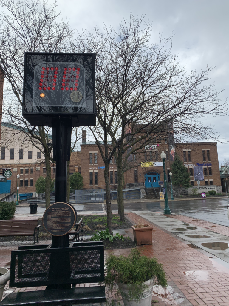
In addition to being a source of Syracuse pride, the shot clock also reminds us how simple an innovation can be! Sometimes, a little math and a dash of electrical engineering in the right place are enough to get the “ball” rolling…So we got to thinking — how easy would it be to make our own?
Those who are already familiar with Arduino can check out these Shot Clock Instructables, which are similar to our design. But for those with no experience, we’ve put together an introductory activity that gets at the basics. Materials are inexpensive, and learning resources for Arduino are widely available online. And remember, the MOST is here to help! You can always reach out to our Student Science Hotline to ask questions or troubleshoot.
In this introductory version of the Arduino shot clock, you can make your own timing devices using fairly basic components! You can even make cool patterns and dancing lights once you get the hang of it.
Instructions:
Required Materials: Arduino Uno, LED bulbs, breadboard, jumper wires, 220Ohm resistors, computer
1: Once you have gathered the required materials for this project, we’re going to start with learning about how to program our arduinos to illuminate an LED! First, you will need to plug your Arduino Uno into your computer using a USB-A to USB-B wire. Afterwards you’ll need to install and open the free Arduino IDE.
2: Upon completing step 1, you’ll need to open a new project, title it how you please, and then click on the tools tab on the top of the window. You’ll need to select the board you’re using (Arduino Uno), and the port that it’s plugged into on the computer, it should specify the Arduino next to the port number.

3. Next we’re going to learn how to send power to an LED directly from one of the pinouts on the Arduino. For this part, you’ll need two jumper wires, a breadboard, an LED, and a resistor, as well as your Arduino and computer. I’ll be running my jumper wires from the pinout #8 and the ground next to pinout #13.
4. From pin #8, you’re going to run your jumper wire to the longer side of the LED. Each numbered row in a breadboard is connected, and the two columns on each half are connected, meaning anything plugged in each section is electrically connected. I ran my jumper from pinout #8 to row 16 on the right side of the breadboard. I connected my LED to the breadboard by connecting the longer side to row 16 on the right side of the breadboard, and the shorter side on row 16 on the left side. LEDs only allow current through one direction, so this is an important orientation. To ensure we don’t send too much power through the LED, we’re going to run a 220Ohm resistor from left row 16 to the the (-) column of the breadboard, this is connected to the ground pinout on the arduino.


5: Now that we’re set up to power the LED through the arduino, let’s go back to our IDE. Above the line that says void setup() { we’re going to declare which pinout the LED is attached to. Since our power is coming from pinout #8, that’s what we’ll declare. You can use any pinout, just make sure that the number you enter here corresponds.
6: Next, we have to set the pin# on the arduino to be used for outputting information. Underneath void setup() { enter the following line of code.

7. Finally, once you’ve completed step 6, you’re ready to start controlling the LED from the arduino itself! For this part, we’re going to program our LED to turn on, wait a second, and turn off. As this is in a part of the code that loops, we’ll add another second delay before the code completes, that way our LED doesn’t immediately turn back on. Underneath the loop section enter your code as follows:

8: Once you’ve completed the code, click on the arrow above your code to upload it to the arduino, then watch as your LED powers on and off! Now that you know how to power LEDs, play with the code to see if you can change the time delays or power multiple LEDs at once using the same techniques!